 Telecommunications Infrastructure Design Standards (TIDS) (Installer Version 2.0)

Steve Scherer RCDD 6/27/2016
This Quick Reference Guide is designed specifically for the Telecommunications Technician
who is doing the actual installation work at Fresno State. This guide has excerpts
from the Fresno State Telecommunications Infrastructure Design Standards (FSTIDS)
that pertain to the actual installation, termination, labeling and testing of the
structured cabling system used on Campus. The sections of the FSTIDS manual are listed
at the beginning of each of the sections in this Guide.
INDEX
PG
3. 568B Jack Standard
4. Testing Results Comp. Dates
Validation of Fiber & Copper
5. Testing Failure Rates
Testing Criteria
Liquidated Damages
6. Convenience Outlets
UPS Service
Horizontal (Station) Cables
7. Faceplate Designations
8. Cable, Jack Colors, Bundling
9. Campus Jack Types
10. Basic/Wall Faceplates
11. Standard/Integrated Fcplte
12. Dual Station Faceplate
13. Data Station Faceplate
14. Wireless Faceplate
15. LCD Projector Faceplate
16. Television Faceplate
17. Blackboard Faceplate
18. Camera Faceplate
19. EMS Faceplate
20. Power Meter Faceplate
21. Cable/Jack Labeling
22. Patch Panel Labeling
23. Certify/Documentation
B8.8-A TIDS
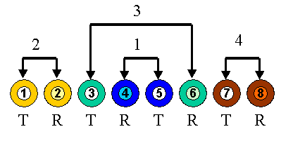
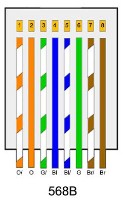
Fresno State uses the 568B Standard shown below:
1.7-D.1 TIDS
1. Testing Results Completion
A mutually agreed upon testing results completion deadline between the Contractor/Vendor
and Fresno State’s Technology Services will be established at the time of the generation
of the Purchase Order or the awarding of the bid. This date will be at least two weeks
(10 working days) prior to the turning over of the building for occupancy. This allows
Technology Services time to validate the test results and insure that all testing
is complete prior to placing copper and fiber into service. All copper horizontal
station cable and fiber optic cable testing will comply with (TIA) ANSI/TIA/EIA-568-B.1
or (ISO) ISO/IEC 11801 Ed.2 Industry Standards, and be done using a current, certified
and calibrated Fluke test instrument. Copper tie-cables and OSP underground cable
only need to be tested for length, opens, shorts, grounds, and crosses.
1.7-D.2 TIDS
2. Validation of Fiber and Copper
Technology Services will conduct tests on ten (10%) percent of the accepted OSP copper and tie-cables on a random basis, if more than one (1%) percent indicate trouble then a second ten (10%) percent will be randomly tested, for any failures found over one (1%), the Contractor/Vendor will be required to repair and retest them.
Fiber Optic Cables and Horizontal Station Cables will also be randomly tested to validate
test results. The failure rate for these is zero (0%) percent. Technology Services
will conduct tests on ten (10%) percent of the fiber and station cable if there are
any failures then a second ten (10%) percent will be randomly tested.
1.7-D.3 TIDS
3. Testing Failure Rates
Tie-cables and OSP underground cables can have up to a one (1%) percent failure rate,
if properly documented. The most common problem with horizontal station cable is split
pairs, if tested properly, these can be identified very easily. Horizontal copper
station cables and fiber optic cables will have zero (0%) percent failures.
1.7-D.4 TIDS
4. Repair Rates
The cost of the initial random testing of copper and fiber will be borne by Technology
Services as part of the cost of doing business. Any additional repair and testing
charges incurred by Technology Services or a third party vendor will be done at the
expense of the Contractor/Vendor at our current non-state hourly rate. The cost will
be the current “time and material” rate of Technology Services for non-state agencies
as determined by the Chancellor’s Office.
1.7-D.5 TIDS
5. Liquidated Damages
If the Work is not completed within the time required, the Contractor may be required
to pay liquidated damages, per day, as based on the Contract or Purchase Requisition.
6.2-A TIDS
A. Convenience Outlets (TIA/EIA-569-A-8.3.2.3.10)
Convenience outlets shall be 120V. Convenience outlets shall be circuited from a normal power panel. On walls adjacent to the rack bay (where the rack bay butts up against the wall), provide one quadplex outlet approximately 12 inches in front of the rack bay and one quadplex outlet approximately 30 inches behind the rack bay.
On the other walls, provide two quadplex outlets per wall up to 15 feet. On walls
longer than 15 feet, provide two duplex outlets.
6.2-A TIDS
C. UPS Service
A dedicated electrical outlet shall be provided for the UPS system. The service shall
consist of one 120V 20A circuit to an L5-30R receptacle and one 120V 30A circuit to
an L5-30R receptacle located behind the rack bay in close proximity to the intended
location of the UPS system. Both branch circuit wiring shall be 10 AWG. The Telecom
Designer and Electrical Designer shall coordinate the electrical service with the
equipment layout. Confirm design draft with Technology Services prior to finalizing.
The UPS system with the power strips for rack service will be provided by Technology
Services.
8.6-A TIDS
A. Horizontal (Station) Cable Type
Horizontal cables shall meet the rating required by the authority having jurisdiction, Technology Services. Assume that all cables shall be CMP (plenum) rated. Horizontal cables shall be twisted pair type, with four twisted pairs, and should have a CMP rated sheath and have a 24” service loop above ceiling at jack location. Service loop at closet end will be determined by the closet size.
8.8-D TIDS
D. Faceplate Designations
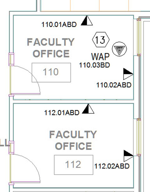
All faceplates will be given a unique faceplate number. It will be determined by the BDF/IDF (Building Distribution Frame or Intermediate Distribution Frame), the room number and the jack number. NOTE: Architectural drawing room numbers are NOT accurate; it is the responsibility of the installer to verify with Technology Services the correct faceplate designation. As a rule, the numbering is usually determined by the assigning the jacks in a clockwise manner in the room. See sample diagram below.
8.7-4 TIDS
DEFINITION OF COLORS FOR JACKS AND CABLES
There is a specific reason for the different colored jacks and cables. They not only
allow identification in patch panels, but also during the process of running additional
cable. Station cables shall have a color jacket as follows:
Blue – Analog/Digital or Data
Yellow – Data 1
White – Data 2
Orange- Power Meters
NOTE: Jacks are the same color as cable jacket
8.3-C-7 TIDS
BUNDLING OF CABLES
Category 6 cables must not be grouped or tied together with ty-warps or tape. Any deformation of the cable could result in erroneous readings and ultimately a failure when certifying the cable. Also “J” hooks are the only accepted way of suspending Cat6 cables from the ceiling. Do not use T-Bar wires, suspended light wires, of other ceiling fixtures for running cable. Also remember that cables will not be placed on fluorescent lights or ceiling tiles. Any bundling of cables will be with Velcro strips and bundled loosely.
8.8-B.1-10 TIDS
JACK CONFIGURATIONS USED ON CAMPUS
There are several different jack configurations used at Fresno State depending on the type of service that the jack will be supplying. While some of them seem similar, they are very different in their configuration and use. They are listed below with a description of their use and a diagram of what they look like.
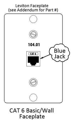
1. Basic/Wall Faceplate (1 Blue Jack)
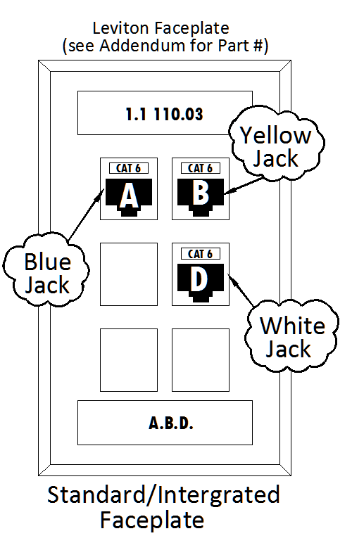
2. Standard/Integrated Faceplate (1 Blue Jack, 1 Yellow Jack, 1 White Jack)
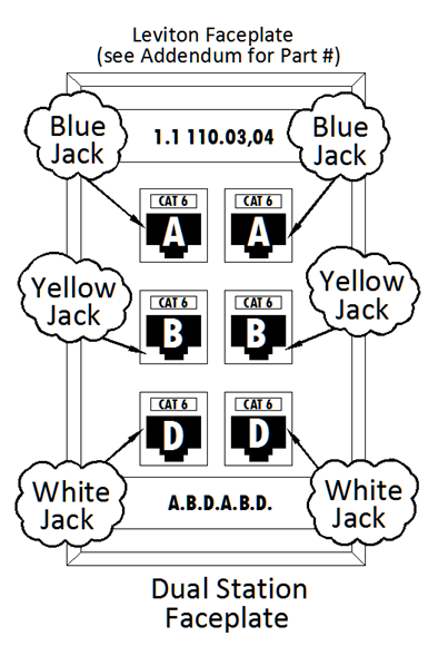
3. Dual Faceplate (2 Blue Jacks, 2 Yellow Jacks, 2 White Jacks)
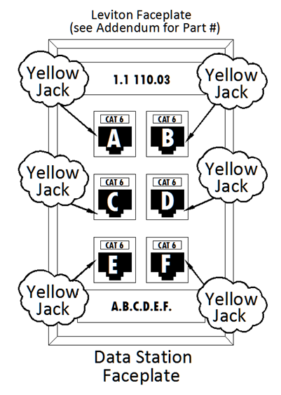
4. Data Faceplate (6 Yellow Jacks)
5. Wireless Access Points (WAP) (2 Yellow Jacks)
6. LCD Projector (PTV) (2 Yellow Jacks)
7. Television (TV) (2 Yellow Jacks)
8. Blackboard (2 Yellow Jacks)
9. Camera (2 Yellow Jacks)
10. Energy Management Systems (EMS) (2 Yellow Jacks)
11. Power Meter (1 Orange Jack)
1.Basic/Wall Faceplate
The Basic module design supports voice or data applications on one telecommunications outlet by one 4-pair Leviton-Plenum Unshielded Twisted Pair (UTP) Category 6 Blue colored cable. A basic design is used for phones, card readers, or to augment an existing work area with additional voice or data capacity.
For classroom and lab situations that do not require any data connections, at least one location for a wall set is required. It will be installed at the required ADA height (48”) with a Category 6 RJ45 jack and faceplate. This faceplate must be stainless steel and have the ability to secure a wall set to it. See Addendum for Leviton Part Number. It will be labeled with the appropriate room, jack and port number.
2.Standard/Integrated Faceplate
The Standard module design supports voice and data applications on three distinct telecommunications outlets by three individual 4-pair Leviton-Plenum UTP Category 6 cables (a blue, yellow, and white cable) each terminates on separate telecommunications connectors (a blue, yellow, and white jack). Faceplate labeling will be done mechanically and the labeling font size will be 24 point, (3/8”). The standard outlet is the most commonly used configuration at Fresno State. Patch panel information will be supplied by Technology Services. The Integrated module design supports complex systems including voice, data, and video applications. An integrated module consists of three or more 4-pair Leviton-Plenum UTP Category 6 cables supporting each terminate on separate telecommunications connectors.
3.Dual Faceplate
In addition to the previous example, there are several other types of faceplate configurations that are used on campus. If there are two adjacent work stations they may both be placed in the same faceplate, as shown in the figure below. In the Dual Station Faceplate, one station uses the jacks on the left side of the faceplate and the second work station uses thee jacks on the right side of the faceplate. There is a blue, yellow and white cable pulled for each station. The blue Leviton Category 6 RJ45 jack is used for voice or data connections, and is always in the uppermost jack cutout. The yellow Leviton Category 6 RJ45 jack is used for primary data connection, and it is in the middle faceplate cutout. The white Leviton Category 6 RJ45 jack is located in the bottom jack cutout. Faceplate labeling will be done mechanically and the labeling font size will be 24 point, (3/8”.) Patch panel information will be supplied by Technology Services.
4.Data Faceplate
Fresno State utilizes a configuration in our computer labs or in locations where there is a high concentration of data connections. These are called Data Station Faceplate connections and may include as many as six data connections. These are all yellow Leviton Category 6 RJ45 jacks and are placed and counted from the top left down. All cables to be pulled are yellow cables. Note that lettering is used for the jack location of the faceplate and numbers are used for the actual jack location in the room. Faceplate labeling will be done mechanically and the labeling font size will be 24 point, (3/8”.)
5. Wireless Access Points Faceplate
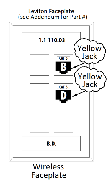
For wireless connections Fresno State will require a faceplate with two connections. They are yellow Leviton Category 6 RJ45 jacks placed on both the faceplate end and the patch panel end of the cable. They are placed the same location as the example below and all vacant ports on the faceplate will have blanks installed on them. The cables that are pulled for them are yellow. This faceplate is almost always in the ceiling and the room faceplate designations require that these faceplates will be assigned faceplate numbers after all of the wall outlets have been identified. Faceplate labeling will be done mechanically and the labeling font size will be 24 point, (3/8”.)
6. LCD Projector Faceplate (PTV)
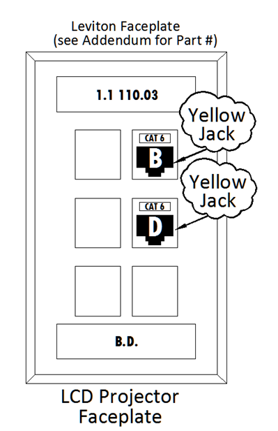
For LCD Projector connections Fresno State will require a faceplate with two connections. They are yellow Leviton Category 6 RJ45 jacks placed on both the faceplate end and the patch panel end of the cable. They are placed the same location as the example below and all vacant ports on the faceplate will have blanks installed on them. The cables that are pulled for them are yellow. This faceplate is always in the ceiling and room faceplate designations require that these faceplates will be assigned faceplate numbers after all of the wall outlets have been identified. Faceplate labeling will be done mechanically and the labeling font size will be 24 point, (3/8”.)
7. Television Faceplate (TV)
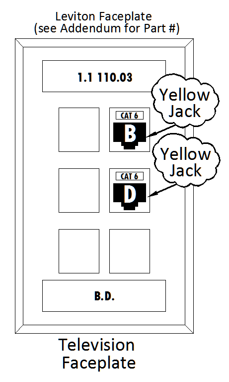
For Television connections Fresno State will require a faceplate with two connections. They are yellow Leviton Category 6 RJ45 jacks placed on both the faceplate end and the patch panel end of the cable. They are placed the same location as the example below and all vacant ports on the faceplate will have blanks installed on them. The cables that are pulled for them are yellow. Room faceplate designations are assigned in room rotation, just like other wall faceplates. The faceplate designations will be assigned by Technology Services. Faceplate labeling will be done mechanically and the labeling font size will be 24 point, (3/8”.)
8. Blackboard Faceplate
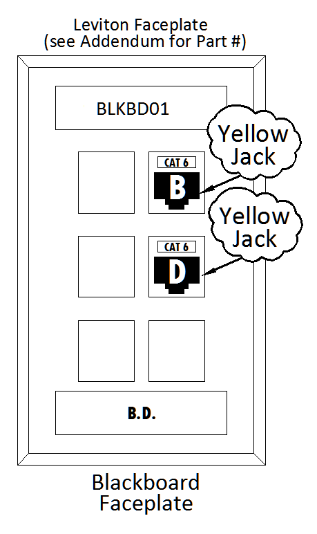
For Blackboard connections Fresno State will require a faceplate with two connections. They are yellow Leviton Category 6 RJ45 jacks (611110-RY6) placed on both the faceplate end and the patch panel end of the cables. They are placed in the same location as the example below and all vacant ports on the faceplate will have blanks installed on them. See Addendum for the correct Superior Essex Cat6 cable Part Number. The faceplate designations require that these faceplates will be assigned patch panel positions 47 and 48 of the last patch panel and labeled BLKBD01B and BLKBD01D on both ends with a mechanical labeler and NOT handwritten. The door or controller will be terminated in a Quickport single gang 6 port faceplate as shown on the right.
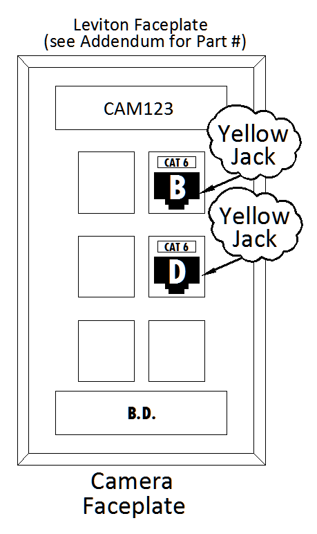
9. Camera Faceplate
For Camera connections Fresno State will require a faceplate with two connections. They are yellow Leviton Category 6 RJ45 jacks (611110-RY6) placed on both the faceplate end and the patch panel end of the cables. They are placed the same location as the example below and all vacant ports on the faceplate will have blanks installed on them. See Addendum for the correct Superior Essex Cat6 cable Part Number. The faceplate designations require that these faceplates will be assigned as CAMXXX, (XXX= faceplate numbers assigned by Technology Services) and both ends will be labeled with a mechanical labeler and NOT handwritten and the labeling font size will be 24 point, (3/8”.) The jacks will be terminated in a Quickport single gang 6 port faceplate as shown on the right.
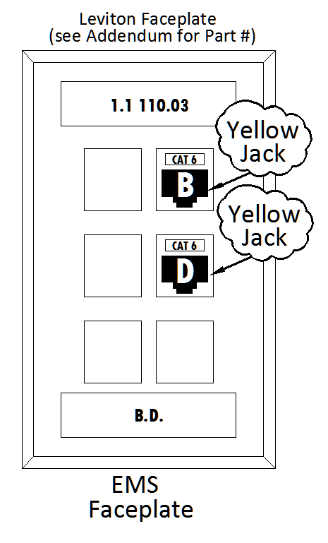
10. Energy Management Systems Faceplate (EMS)
For EMS connections Fresno State will require a faceplate with two connections. They are yellow Leviton Category 6 RJ45 jacks (611110-RY6) placed on both the faceplate end and the patch panel end of the cables. They are placed the same location as the example below and all vacant ports on the faceplate will have blanks installed on them. See Addendum for the correct Superior Essex Cat6 cable Part Number. The faceplate designations will be assigned by Technology Services and by no means are ever terminated INSIDE the EMS cabinets. Cables are identified on both ends with a mechanical labeler and NOT handwritten. The EMS Jack will NOT be terminated inside the EMS cabinet and will be terminated in a Quickport single gang 6 port faceplate as shown on the right.
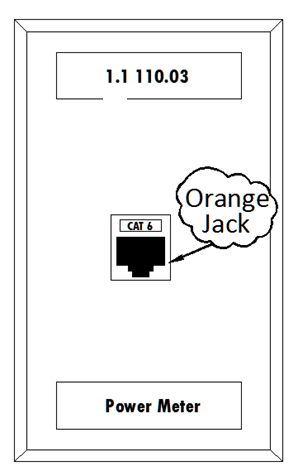
11. Power Meter Faceplate
For Power Meter connections required in newer buildings Contractor will place an Orange Jack in a single port faceplate (Note: This is the only circuit that will use a single port at Fresno State). If Power Meter is located in the building, See Addendum for the correct Superior Essex Cat6 cable Part Number. If meter is located outside of the building then Superior Essex Cat 6 OSP Broadband BBD cable will be used. Locations will be determined by Technology Services. Faceplate labeling will be done mechanically and the labeling font size will be 24 point, (3/8”.)
8.9-A TIDS
HOW CABLES ARE LABLED
Labels, tags, and straps shall be high quality that will endure over the life of the
cable plant. Hand written labels are NOT acceptable. Cable labels shall be self-laminating.
Cable labels shall be provided at both ends of the cable and installed on the cable
jacket within ten inches of the termination at the BDF/IDF and within 2 inches of
the faceplate end.
8.9-C TIDS
Patch Panel Labeling
Each used port of a modular patch panel shall be labeled with ROOM, FACEPLATE NUMBER,
and JACK position. Example 124C.02A for an individual cable. Technology Services to
provide “Cut Sheets” for labeling and termination
Outlet Labeling
Each faceplate shall be labeled with ROOM, FACEPLATE NUMBER, and JACK position. Example:
361.02A for each cable. Technology Services to provide “Cut Sheets” for labeling and
termination.
Patch Cord Color
All patch panel to switch cables are Yellow, regardless of color of jacks. Patch panel ports 1-12 & 25-36 will terminate on switch
ports 1-24 and patch panel ports 13-24 & 37-48 will terminate on switch ports 25-48.
Patch Panel Labeling
Each used port of a modular patch panel shall be labeled with ROOM, FACEPLATE NUMBER, and JACK position. See below. Example 124C.02A for an individual cable. Patch panel labeling will be done mechanically and the labeling font size will be 18 point, (3/16”).
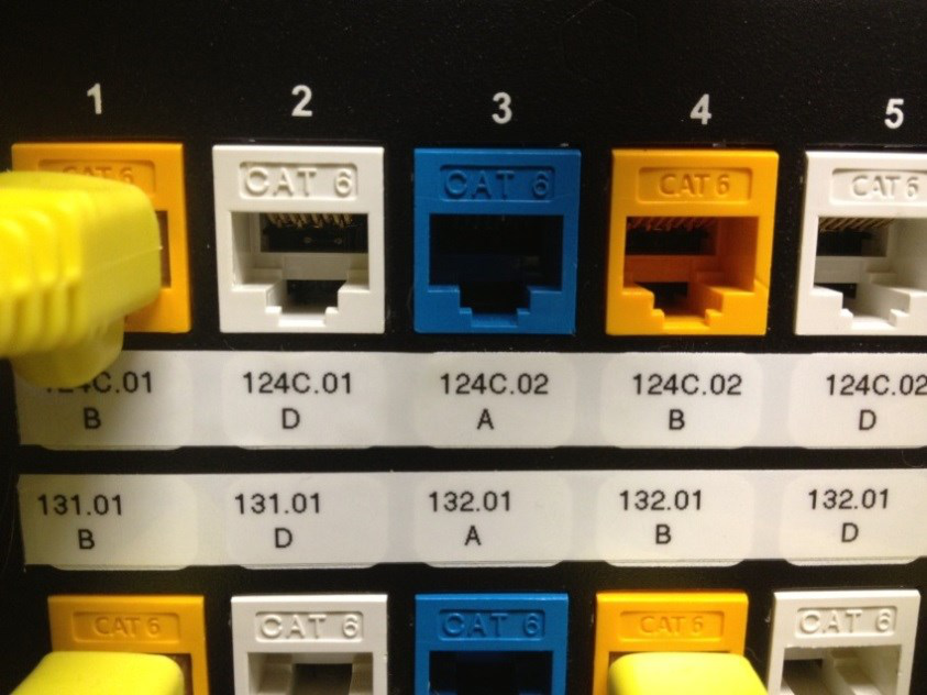
Technology Services WILL provide “Cut Sheets” for labeling and termination. See example
below.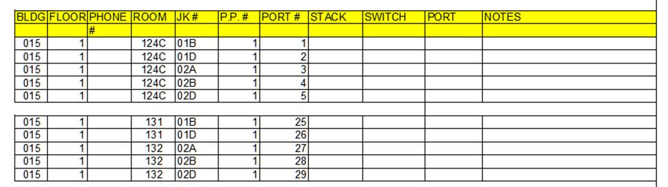
8.10-1 TIDS
DOCUMENTATION REQUIREMENTS
Before executing any performance testing, the Contractor shall present a test plan
to Technology Services for approval. Test equipment must have proof of calibration
prior to the start of any testing. All testing will be done in accordance with (TIA)
ANSI/TIA/EIA-568-B.1.All test results will be examined and approved by Technology
Services. OSP and tie-cable copper test results cannot have more than a 1% failure
rate and fiber optics and horizontal station cable test will have a zero percent failure
rate.
8.10-3 TIDS
The Contractor shall complete all testing and deliver copies of all test results to Technology Services. These records will be on a CD/DVD and on hardcopy. Contractor will deliver “as built” drawings on CD/DVD and hardcopy and these documents will include conduit/cable locations, depth of any buried facilities, and measurement for the placement of conduits or underground facilities. Digital drawings will be delivered to Technology Services in an ACAD format (Rev 2012 or later).
This PDF is provided as a print-only reference document and may not be fully accessible to users of assistive technology. For more information, please visit Title II Rule on Digital Accessibility page.